14 Jan 2026
Note: this blog post is only like half way complete. I may or may not circle back to it. The stuff on octahedral mappings is all finished, but the impostor application below is not.
Ryan Brucks published an article describing “octahedral impostors” in 2018. The basic idea is to to take photos of some subject at octahedral lattice points, record them to an atlas, then reconstruct those photos in a particle.
The octahedral mapping is simply one way to convert between a flat coordinate system and a spherical coordinate system. It is notable because it does not use any trig functions, making it suitable for use in realtime graphics.
This is what an octahedron looks like:
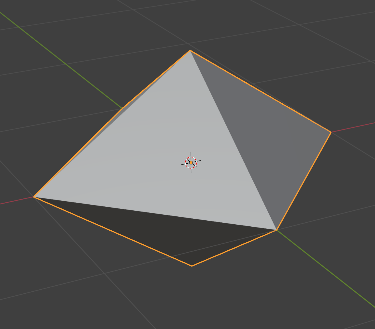
It is a polyhedron with 8 triangular faces and 6 vertices. The equator is a square.
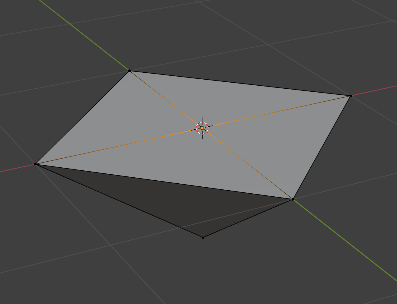
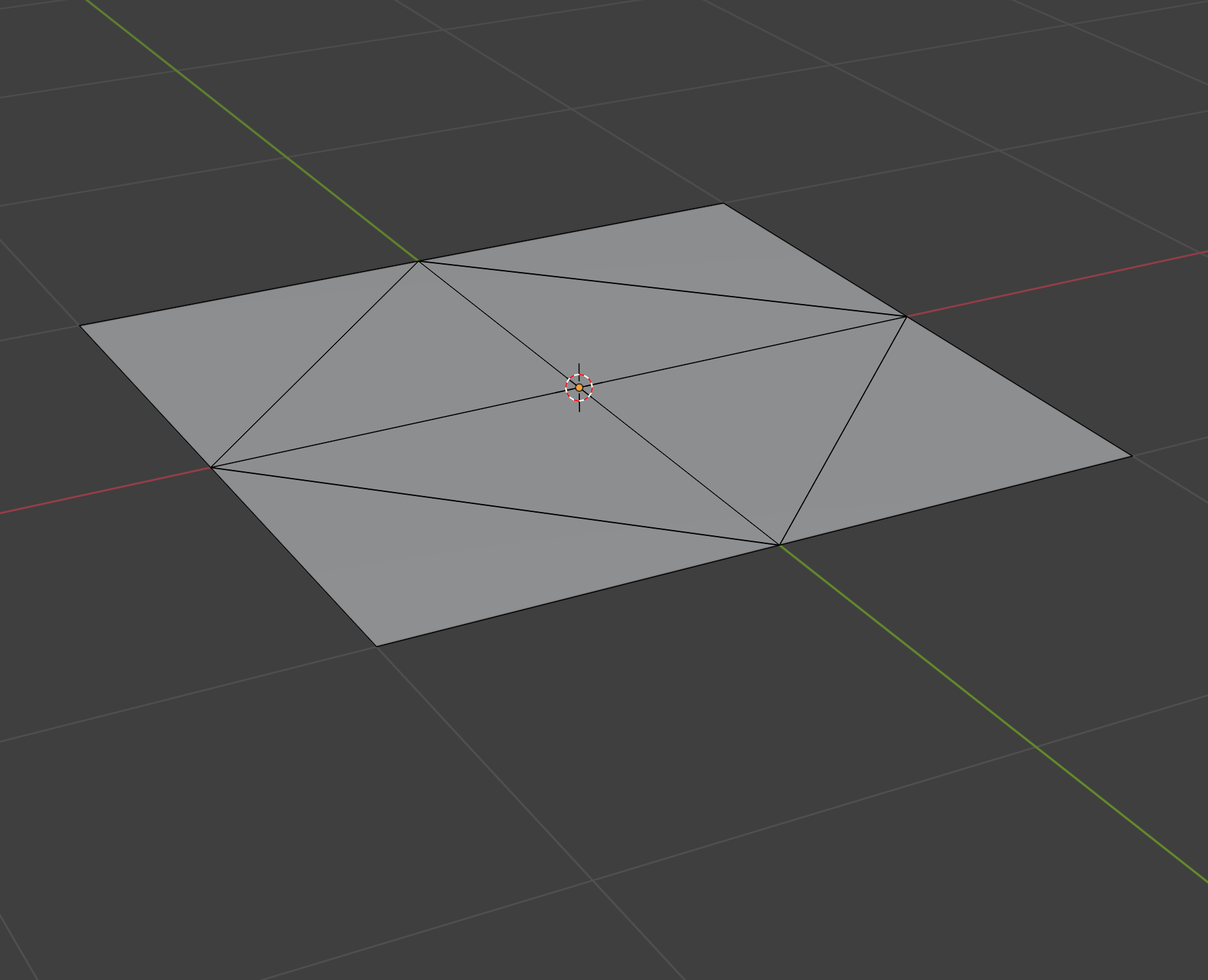
Let’s work out how we’d convert this octahedron to a plane. First, we project the upper hemisphere onto the xz plane:
Next, we effectively need to “rotate” the triangles in the lower half around those diagonal edges. We can cheat by first reflecting the bottom vertex of each triangle about its diagonal edge:
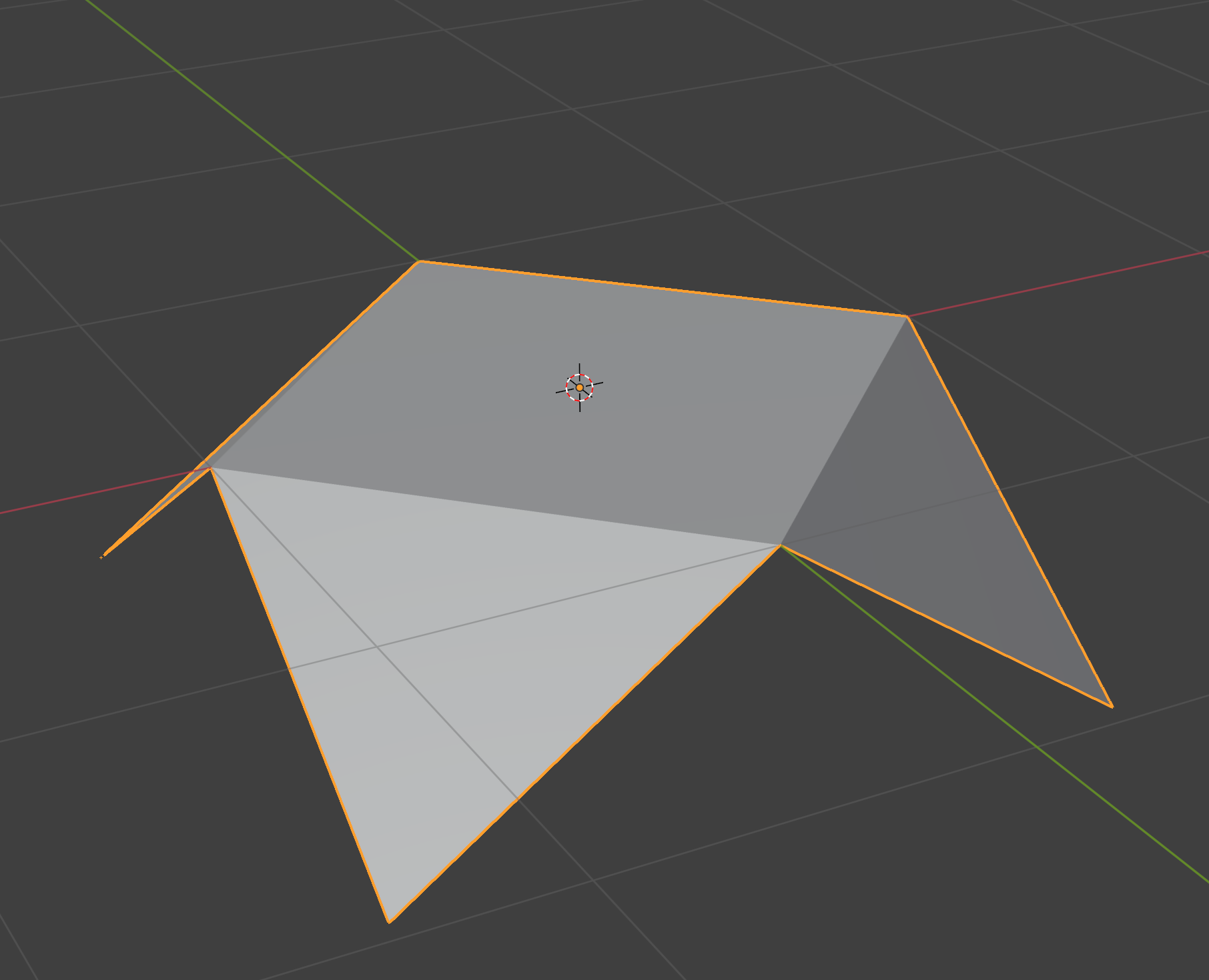
Finally, we can just project those points in the lower hemisphere onto the xz plane:
Viewed head on, we can see a very beautifully symmetric unwrapping:
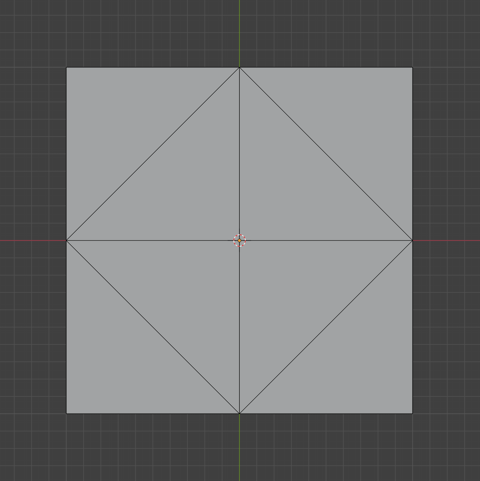
Note that we never actually did any rotations, so there no trig! Here’s the same procedure in code:
// Convert unit octahedron to a [-1,1] x [-1,1] patch on xz plane.
float3 octahedron_to_plane(float3 p) {
  if (p.y >= 0) {
    // Project upper hemisphere onto xz plane.
    p.y = 0;
    return p;
  }
  // First, reflect the lower hemisphere's points about their diagonal.
  p.x = sign(p.x) * (1 - abs(p.x));
  p.z = sign(p.z) * (1 - abs(p.z));
  // Then project onto the xz plane.
  p.y = 0;
  return p;
}
We can generalize this procedure to unwrap any spherical object by just switching norms:
// Convert unit sphere to a [-1,1] x [-1,1] patch on xz plane.
float3 octahedron_to_plane(float3 p) {
  // Switch from L2 to L1 norm. This basically bends a sphere to an octahedron.
  float l1_norm = abs(p.x) + abs(p.y) + abs(p.z);
  p /= l1_norm;
  // Then unwrap.
  if (p.y < 0) {
    p.x = sign(p.x) * (1 - abs(p.x));
    p.z = sign(p.z) * (1 - abs(p.z));
  }
  p.y = 0;
  return p;
}
Here’s a quick demo showing what that norm conversion does to a unit sphere:
Going from plane to octahedron is just the same thing backwards:
// Convert a [-1,1] x [-1,1] patch on xz plane to a unit sphere.
float3 plane_to_octahedron(float3 p) {
  float l1_norm = abs(p.x) + abs(p.z);
  if (l1_norm > 1) {
    // Reflect lower hemisphere's point about their diagonal.
    p.x = sign(p.x) * (1 - abs(p.x));
    p.z = sign(p.z) * (1 - abs(p.z));
  }
  p.y = 1 - l1_norm;
  return normalize(p);
}
If you’d like more discussion on this topic, I recommend the spherical geometry section in the PBR book.)
We might only want to map the upper hemisphere to a plane. In that case, we can first note that in the standard octahedral mapping, the inner diamond of the [-1,1] x [-1,1] square gets mapped to the upper hemisphere. So all we have to do is first remap our input to that diamond via a scale and 45 degree rotation, map it, then rotate it back. The code is still very simple:
// Convert unit sphere to a [-1,1] x [-1,1] patch on xz plane.
float3 hemi_octahedron_to_plane(float3 p) {
  // Rotate 45° and scale to fit square into diamond
  float x_rot = (p.x + p.z) * 0.5;
  float z_rot = (p.z - p.x) * 0.5;
  p.x = x_rot;
  p.z = z_rot;

  float l1_norm = abs(p.x) + abs(p.y) + abs(p.z);
  p /= l1_norm;
  if (p.y < 0) {
    p.x = sign(p.x) * (1 - abs(p.x));
    p.z = sign(p.z) * (1 - abs(p.z));
  }
  p.y = 0;

  // Rotate back.
  x_rot = p.x - p.z;
  z_rot = p.x + p.z;
  p.x = x_rot;
  p.z = z_rot;

  return p;
}
Here is that transform, visualized:
If we didn’t do that scale and rotate, this is what it would look like:
I will leave the plane -> hemi-octahedron code as an exercise for the reader.
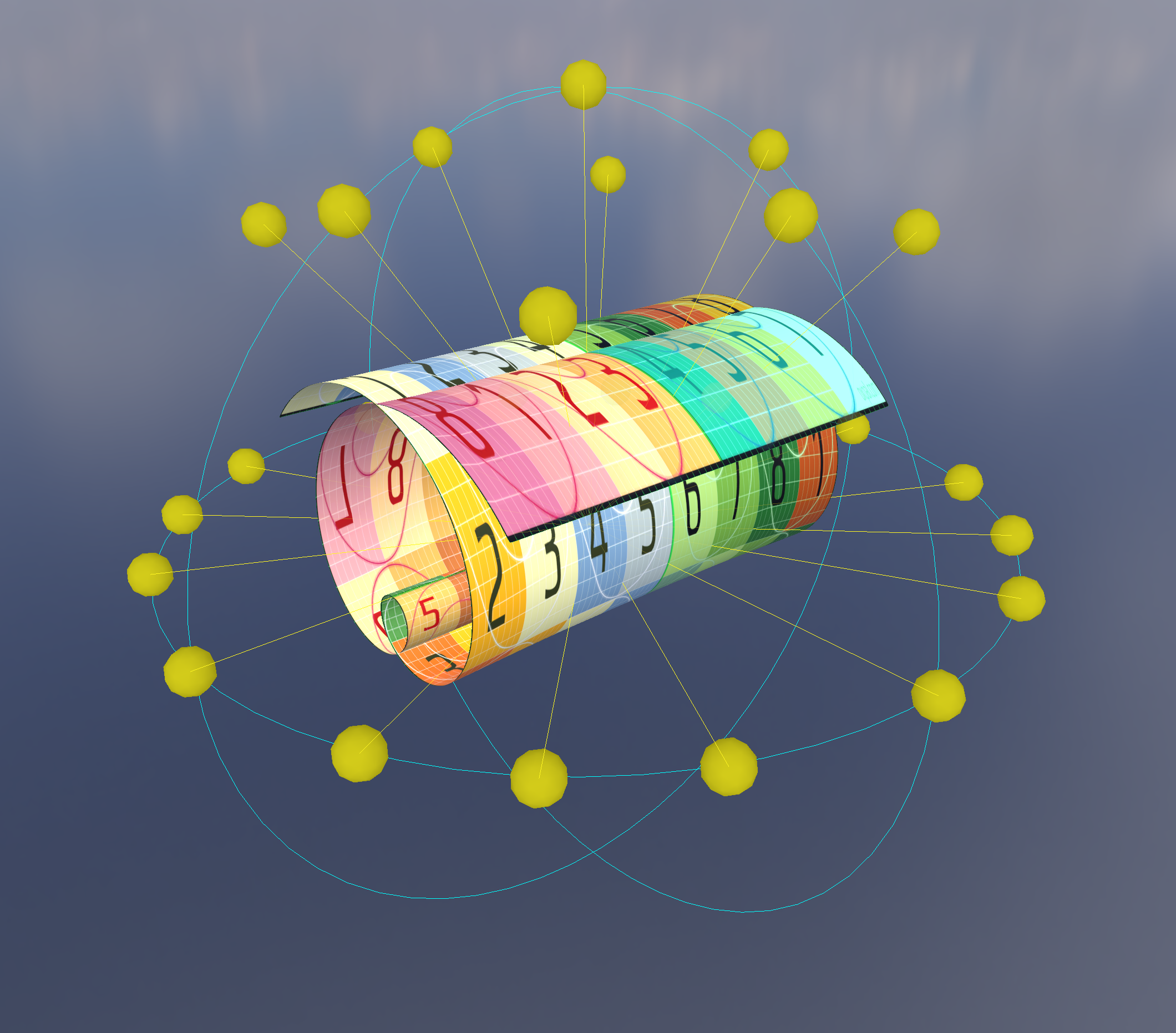
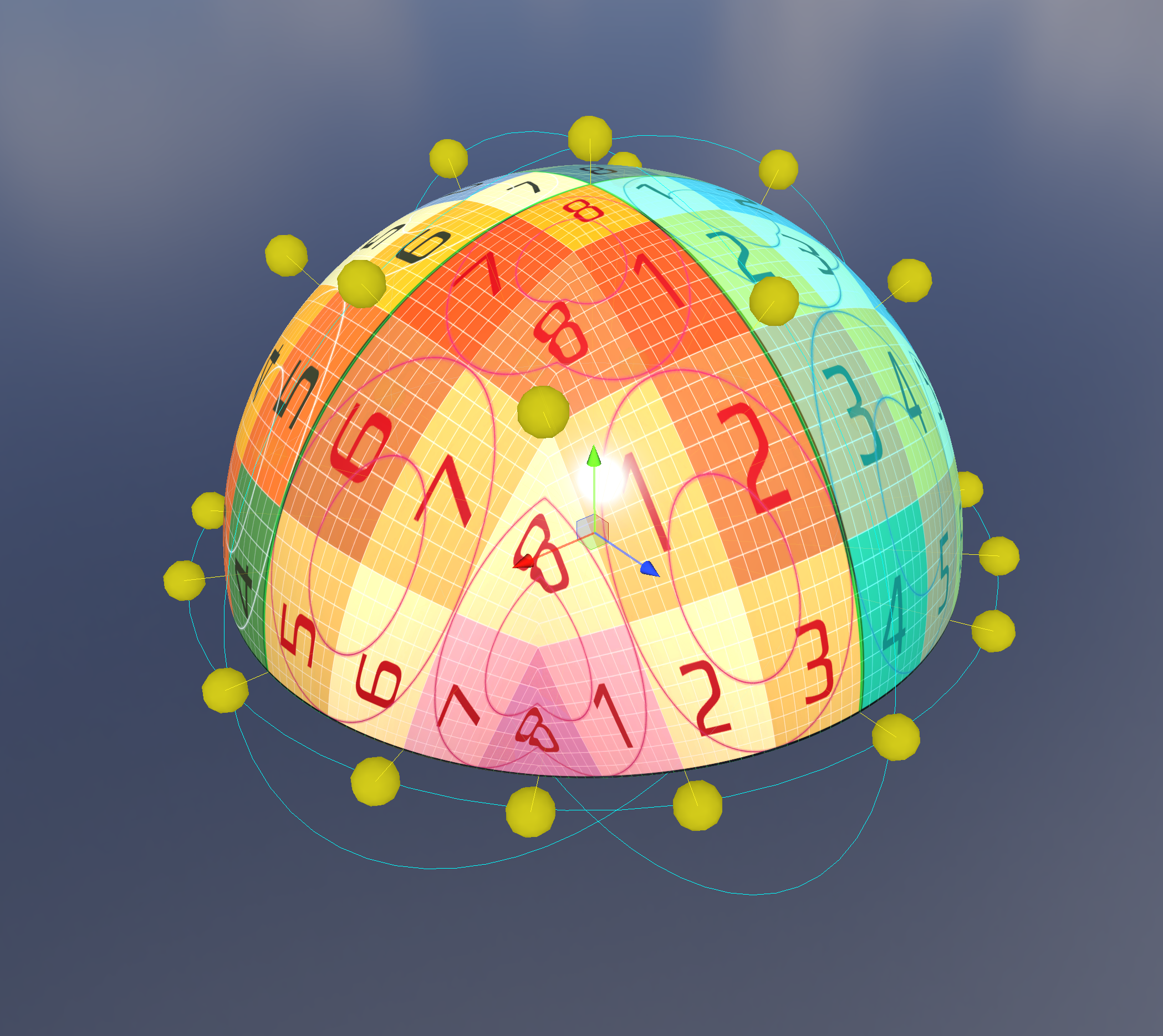
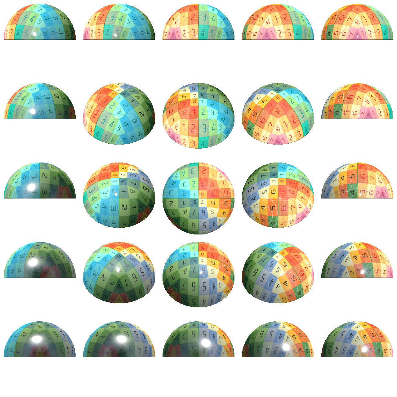
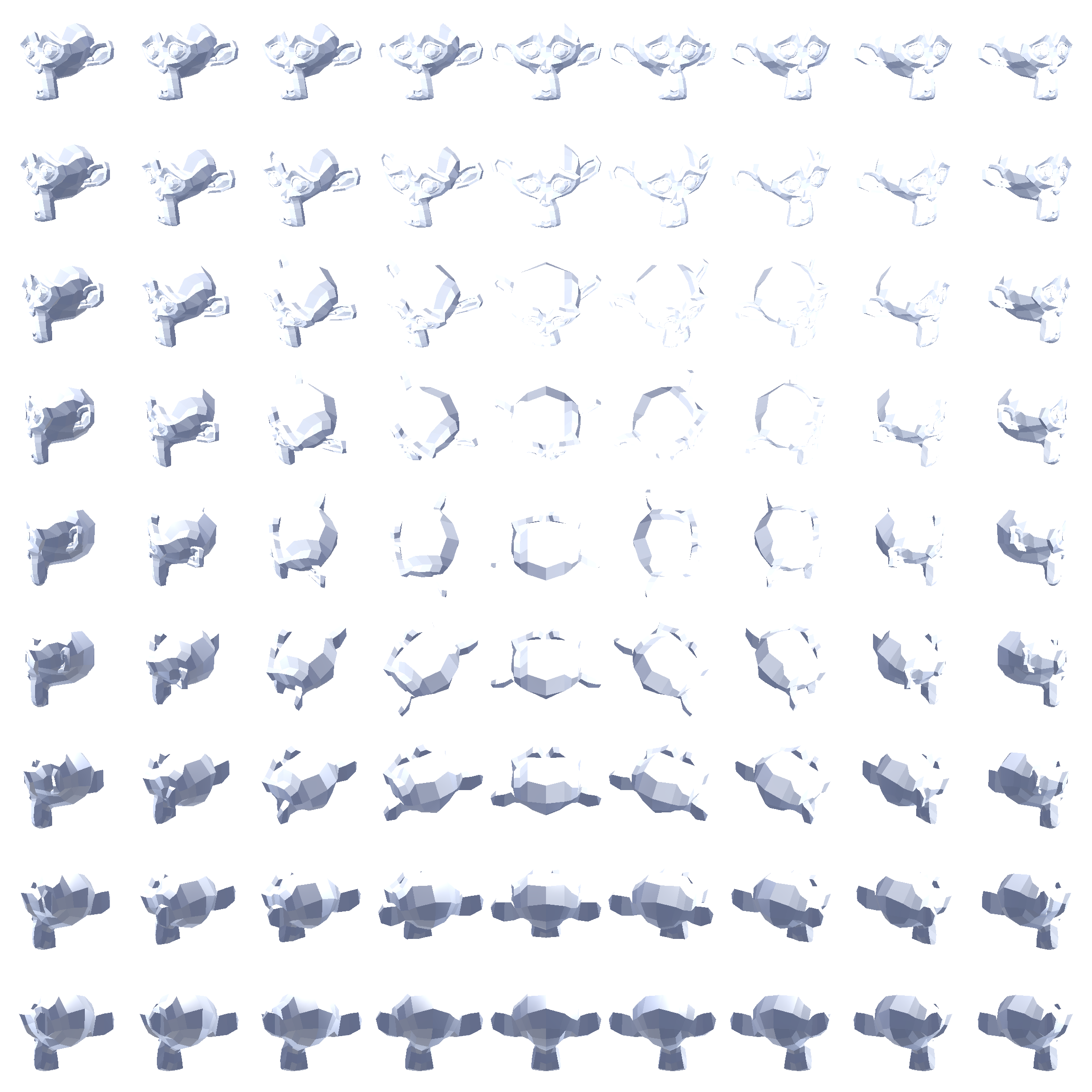
With this mapping, we can write some code to spawn cameras at the lattice points of an octahedral-mapped hemisphere, pointing in at some target object, and generate an atlas of images taken at different angles:
We can then write a naive particle shader which computes its nearest lattice point and simply renders that image.
We can simply compute the direction from the camera to the particle’s center, map that to 2D using the hemi-octahedral mapping, then find the nearest lattice point by rounding. We can also rotate the particle to the same orientation that the photo was taken at to avoid any weird behavior when viewed top down.
That looks like this:
The popping is pretty awful! Can we do better?
Brucks describes a “virtual frame projection” method. I’ll let him explain it:
Looking back to the ‘virtual grid mesh’ above, we can see that for any triangle on the grid, it has 3 vertices. So if we want to blend smoothly across this grid, we need to be able to identify the 3 nearest frames. And remember how using a sprite caused messed up projection of just one frame? Well it turns out the same thing happens when you try to reuse the projection from one frame for another! This is a pain. So you actually have to render a virtual frame projection for the other 2 frames to simulate their geometry. While using the mesh UVs for one projection and ‘solving’ the other two does work, it falls apart for lower (~8x8) frame counts because the angular difference can be so great between cards that you see the card start to clip at grazing angles (not shown in any videos yet). As a compromise, the shader does not use ANY UVs right now. It solves all 3 frames using virtual frame projection in the vertex shader and then uses a traditional sprite vertex shader. The only downside is at close distances you occasionally see some minor clipping on the edge but it is much more acceptable this way.
Lost? Me too! I found this paragraph extremely confusing - it’s what motivated me to write this article.
As near as I can tell, what he’s describing is that you retrieve the nearest 3 lattice points and do a barycentric interpolation. He’s also trying to clarify that you can’t just use the uvs from one lattice point to sample another - you have to calculate each lattice point’s uvs separately. (I suppose that that level of optimization-first thinking is required when you’re building for Fortnite!)
You then render the blended color that on a standard facing quad primitive.
To start, I calculate the ray from the camera to the origin of the particle’s coordinate system. I use that position for my barycentric interpolation.
That looks like this:
Huh. Looks a lot worse than his demo. What are we doing wrong?
Could it just be our choice of mesh that makes our results look bad? Here’s Suzanne:
Maybe it looks a little better?
The mesh that Brucks shows off in his blog post has radial symmetry and smooth normals, which might be responsible.
You can also see some artifacts appearing in open space. This was caused by a couple things:
3 is crucial - with that correction in place, you can pack your atlas pretty tightly. Here’s Suzanne with that correction in place:
Here’s the atlas. Pretty tight packing - could probably be optimized a little further though:
After stepping away for a bath, the issue occurred to me.
I was calculating the lattice point based on the direction from the
camera to the particle center. With barycentric interpolation in place,
we would be better off using a per-pixel ray intersection with the
impostor’s bounding sphere. Concretely: we want to sample the lattice
points whose cameras have a direction most closely matching the standard
view direction. This is found by simply going from the particle’s
bounding sphere origin to the surface along -viewDir,
projecting that to 2d, then rounding to lattice points as normal.
This seems to help a bit, but it’s not night and day. I didn’t capture any videos here, but the next gen uses this tech.
So far we’ve only been rendering pre-lit images of our subject on an unlit particle. Can we do better? What if we captured the albedo, normal, metallic gloss, and position, then lit it with a standard surface shader?
The results look a bit better - specular is much better approximated now:
I continued to spin my wheels for a couple days. I re-read Brucks’ article several more times, and came to a couple conclusions:
I found his description on this video useful:
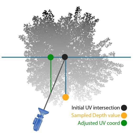
This version blends the three nearest frames using a single parallax offset (similar to a bump offset). This is the version of impostors used in FNBR on PC and Consoles. It was used on mobile originally but switched back to single frame at last minute since we were compositing them into HLODs and thus rendering lots of them.
That single parallax offset is explained by this image:
My buggy implementation looks promising - see how the eyes are much sharper now?
It is still very, very poppy, unlike Brucks’ demo. I must be doing something wrong.
Note: I stepped away from this project and don’t plan to revisit it soon. If I do, I’ll post updates in a followup and link to it from here.